
Model equations
A fixed bed in Mocca is a one-dimensional, axially dispersed plug flow model of a packed column, as in Haghpanah et al. (2013). The gas is ideal, flow follows Darcy's law, mass transfer to the sorbent is a linear driving force, and the energy balance covers the gas, the sorbent and the column wall. The beds are connected to the feed, products and each other through flow devices (valves and flow controllers), whose settings change from step to step of the cycle.
All quantities are in SI units. The symbols are listed in the nomenclature at the end of this page, with the inputs they come from.
Fixed bed
Component mass balance
For each component
Momentum: Darcy's law
The superficial velocity follows Darcy's law with the Kozeny–Carman (Blake–Kozeny) permeability of a packed bed,
This is the viscous (laminar) term of the Ergun equation; the inertial term is not included. The interstitial velocity is permeability to add_bed! to override
Axial dispersion
where diffusivity of Gas, that of the first component if given per component) and dispersion_velocity or dispersion in add_bed! to fix it yourself.
Adsorption rate: linear driving force
This is macropore diffusion control: the particle porosity Adsorbent set the rate.
Isotherm: dual-site Langmuir
The affinities are on a concentration basis (m³/mol), and the saturation capacities in mol per m³ of adsorbent, or in mol/kg with basis = :mass, which Mocca multiplies by the adsorbent density. The single-site langmuir isotherm has equilibrium_loading and isotherm_table, which report mol/kg.
The pure-component isotherms of zeolite 13X from Haghpanah et al. (2013), at three temperatures. CO₂ is held far more strongly than N₂, and both less at higher temperature, so the heat released by adsorption, which warms the bed, lowers what it can hold: 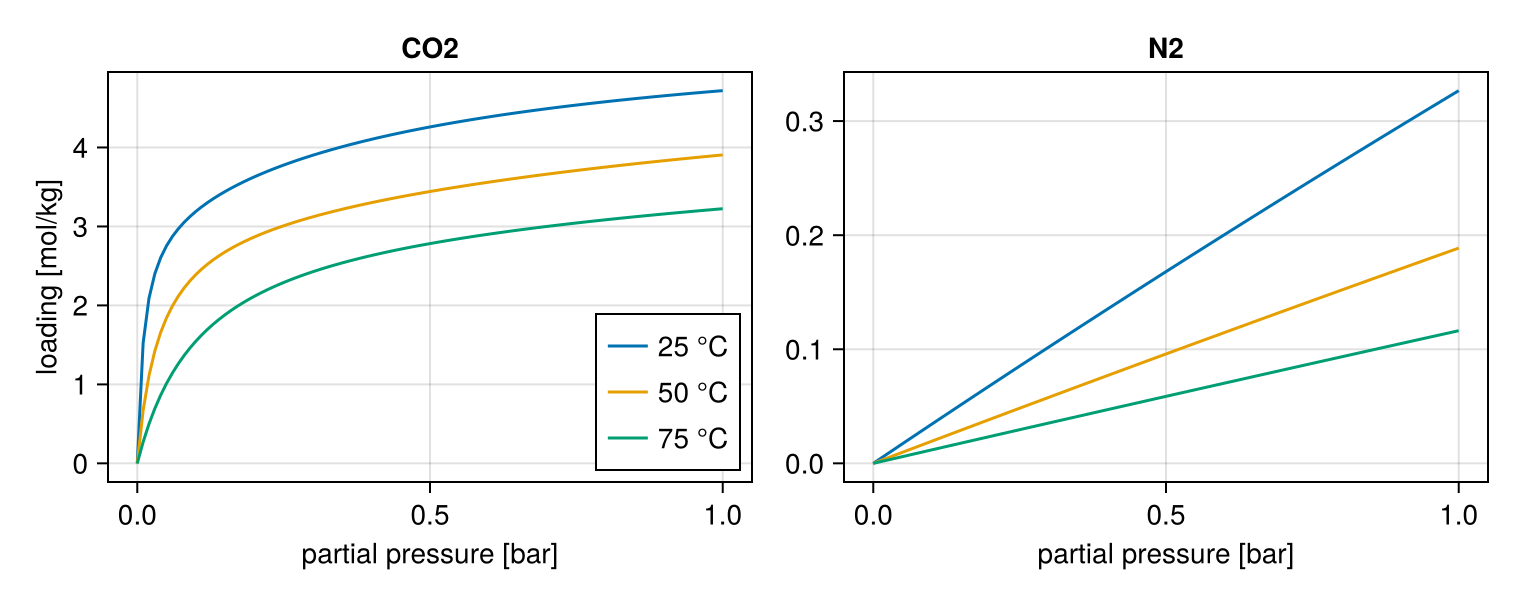
The heat of adsorption of each component is constant, the average of its two site energies weighted by their capacities at the reference temperature reference_temperature, default 298.15 K):
Energy balance of the column
Written in terms of temperature and pressure:
with molar heat capacities of the gas and the adsorbed phase from the per-mass values of each component,
Wall energy balance
At both ends the wall conducts heat to the surroundings at
Thermal options
The thermal keyword of add_bed! chooses the energy model:
thermal | Energy model |
|---|---|
WithWall() (default) | Column and wall energy balances, as above |
Adiabatic() | Column energy balance without the wall term ( |
Isothermal(T) | Temperature fixed at T, no energy balance |
Flow devices and boundary conditions
Each end of a bed (:bottom at :top at
In each step of the cycle every device is closed, a valve or a flow controller:
| Law | Flow |
|---|---|
| Closed | |
LinearValve | |
VolumetricFlow (flow controller) |
Here
By default a valve has the conductance of half a cell at the bed end it is attached to, conductance to a step to model a smaller valve.
During pressurisation, blowdown and evacuation, the pressure on the far side of the valve moves exponentially from where the step starts to where it ends:
with ramp_rate (default 0.5 s⁻¹) of the step or the Process. A blowdown from 1 to 0.1 bar at three ramp rates; at the default rate the pressure on the far side of the valve has made 99% of its change after about 10 s: 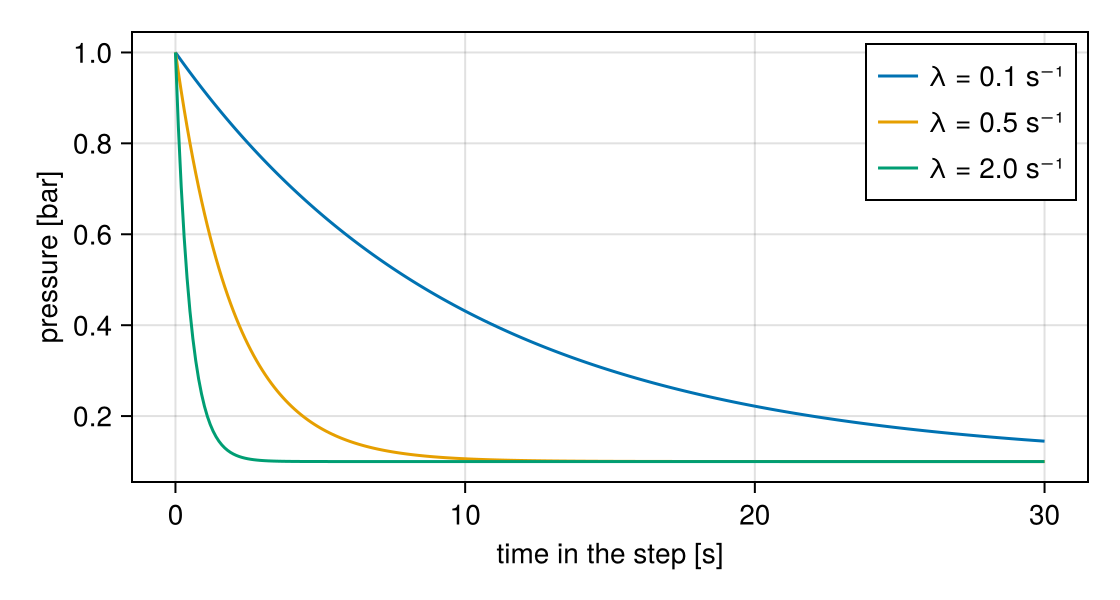
For the four-step VSA cycle this gives the boundary conditions of Haghpanah et al. (2013):
| Step | Bottom ( | Top ( |
|---|---|---|
| Pressurisation | feed valve, | closed |
| Adsorption | feed at velocity | product valve at |
| Blowdown | closed | product valve, |
| Evacuation | vacuum valve, | closed |
Performance
performance measures a process over its last simulated cycle, from the streams through its devices. The device roles (see add_device!) say which streams count. For the key component key_component is given to Process), with
with
The energy counts a vacuum pump on every outlet device (roles :product, :extract, :waste) while it discharges below ambient pressure, and a compressor on every inlet device (:feed, :light_inlet) while it delivers above ambient pressure. Both compress adiabatically between the ambient pressure
reported in kWh per tonne of key component. ambient_pressure (101325 Pa), pump_efficiency (0.72) and heat_capacity_ratio (1.4) of the Process. Haghpanah et al. count the vacuum pumps only; vacuum_pump_energy gives the energy of one device, to report it their way.
Steady state of the cycle
The cycle maps the state of the beds at its start,
Numerical method
Each bed is divided into ncells equal cells (30 by default). Fluxes between cells are two-point, with upwinded advection, and time stepping is fully implicit (backward Euler), solved by Newton's method with exact derivatives from automatic differentiation. Each step of the cycle starts with time steps of first_dt that double up to max_dt (see TimeStepping), which carries the solver through the abrupt start of a step. Gradients for optimisation come from the adjoint of the same discrete equations.
Nomenclature
| Symbol | Meaning | Unit | Set by |
|---|---|---|---|
| Column cross-section, | m² | Column radius | |
| Affinity at infinite temperature, sites b and d | m³/mol | isotherm b0, d0 | |
| Gas concentration of component | mol/m³ | state | |
| Heat capacity of adsorbed component | J/(kg·K) | Adsorbent adsorbed_heat_capacity | |
| Heat capacity of gas component | J/(kg·K) | Gas heat_capacities | |
| Heat capacity of the adsorbent | J/(kg·K) | Adsorbent heat_capacity | |
| Heat capacity of the wall | J/(kg·K) | Wall heat_capacity | |
| Valve conductance | m³/(s·Pa) | step conductance | |
| Particle diameter | m | Adsorbent particle_diameter | |
| Axial dispersion coefficient | m²/s | computed, or add_bed! dispersion | |
| Molecular diffusivity | m²/s | Gas diffusivity | |
| Molar flow through a device | mol/s | state | |
| Heat transfer coefficient, bed to wall and wall to ambient | W/(m²·K) | Column inner_heat_transfer, outer_heat_transfer | |
| Bed permeability | m² | computed, or add_bed! permeability | |
| Axial thermal conductivity of the bed | W/(m·K) | Column axial_conductivity | |
| Thermal conductivity of the wall | W/(m·K) | Wall conductivity | |
| Column length | m | Column length | |
| Molar mass | kg/mol | Gas molar_masses | |
| Pressure | Pa | state | |
| Loading and equilibrium loading | mol/m³ adsorbent | state | |
| Saturation capacity, sites b and d | mol/m³ adsorbent | isotherm qsb, qsd | |
| Inner and outer radius of the column wall | m | Column radius, outer_radius | |
| Gas constant, 8.314 | J/(mol·K) | ||
| Gas and sorbent, wall and ambient temperature | K | state; Column ambient_temperature | |
| Superficial and interstitial velocity | m/s | state; step velocity | |
| Gas mole fraction | – | state | |
| Internal energy of adsorption, sites b and d | J/mol | isotherm ΔUb, ΔUd | |
| Bed porosity (void fraction between particles) | – | Column porosity | |
| Particle porosity | – | Adsorbent particle_porosity | |
| Heat capacity ratio and efficiency of pumps and compressors | – | Process | |
| Pressure ramp rate | 1/s | step or Process ramp_rate | |
| Gas viscosity | Pa·s | Gas viscosity | |
| Density of the adsorbent and of the wall | kg/m³ | Adsorbent density, Wall density | |
| Tortuosity | – | Adsorbent tortuosity |